
Moe's Tech Blog
[OO Design Foundation] Steps to Creating Well Designed Software - 6. Activity Diagram 본문
소프트웨어 디자인/Notes
[OO Design Foundation] Steps to Creating Well Designed Software - 6. Activity Diagram
moe12825 2022. 6. 14. 10:53- Is used to describe workflows or business process
Action and Flows
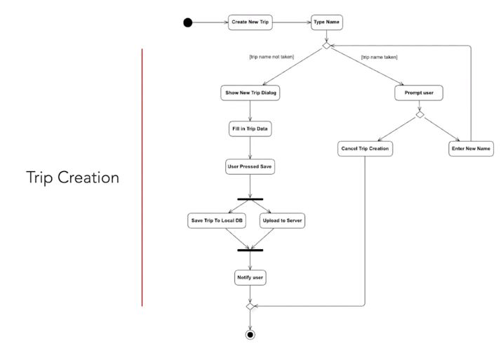
- Activity diagram is started with an intial node drawn as a small filled circle (called initial node)
- Flow is represented by an arrow with an open arrowhead

Decision Node
- Activity diagram can also express conditional logic
- It is represented by a diamond '♢'
- It has a single incoming flow and two or more outbound flows
- Each outbound flow has a guard placed inside square brackets
- The guard need to be mutually exclusive

- After a decision, the flows can be merged using a merge activity

Concurrent Flow
- Activity diagrams support parallel behavior.
- To express concurrent flows, a fork drawn as a thick horizontal line is used:

Ending the Workflow
- Final node is used to indicate the end of workflow
- Final node is represented as a filled circle placed inside a hollow circle

Example
References
- UML and Object-Oriented Design Foundations - https://www.udemy.com/course/uml-and-object-oriented-design-foundations/
'소프트웨어 디자인 > Notes' 카테고리의 다른 글
'소프트웨어 디자인/Notes' Related Articles
more


